
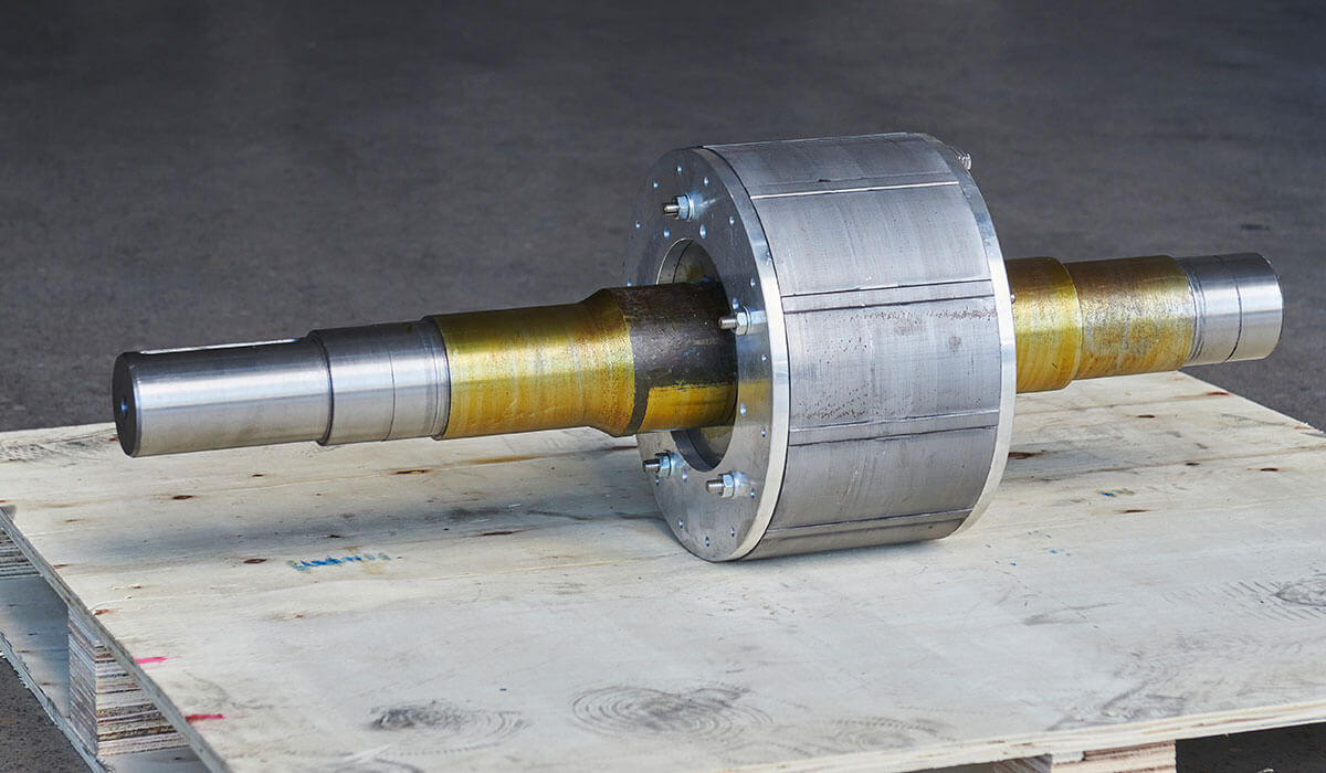
Modern machinery relies heavily on electric motors, which are found in a wide range of applications, including automobiles, industrial machinery, HVAC systems, and household appliances. At the heart of these motors is the rotor—a critical component responsible for converting electrical energy into mechanical rotation. The rotor, the motor’s moving component, interacts with the stator’s magnetic field to generate torque and motion, making it vital to the motor’s operation.
At Zhenli Motor, a professional electric motor manufacturer in China, we recognize that the rotor’s design and construction directly impact the motor’s speed, torque, and overall efficiency, making rotor design a key factor in achieving optimal performance across industrial, commercial, and automotive applications. Understanding the function, structure, and behavior of the rotor is crucial for improving motor performance, enhancing energy efficiency, and preventing mechanical failures.
In this article, Zhenli Motor will explain the different types of electric motor rotors, their functions, working principles, and the key considerations for choosing or designing the right rotor for your specific needs.
What is an electric motor rotor?
The electric motor rotor is the rotating component inside an electric motor that converts electrical energy into mechanical motion. It works together with the stator — the stationary part of the motor — to generate the rotational force, or torque, required to drive machinery, appliances, vehicles, and other systems. Mounted on a shaft, the rotor delivers mechanical power to external components such as conveyor belts, fans, pumps, or vehicle wheels.
How the rotor works
When the motor is powered by electricity, the stator produces a rotating magnetic field that interacts with the rotor in different ways depending on the motor type:
- Induction motors: The magnetic field induces an electric current in the rotor’s conductive bars (often copper or aluminum). This induced current creates its own magnetic field, which interacts with the stator’s field and causes the rotor to rotate.
- Synchronous and brushless DC motors: The rotor includes permanent magnets or direct current windings that stay synchronized with the stator’s rotating magnetic field, ensuring smooth and continuous rotation.
This electromagnetic interaction transforms electrical energy into mechanical energy, turning the rotor and driving the shaft connected to external machinery. Without the rotor, the motor would not produce any motion — it would remain just an electromagnetic assembly.
Key features of the rotor
- Core: Made of laminated steel sheets to provide a path for magnetic flux and reduce energy losses caused by eddy currents.
- Shaft: The central axis that supports the rotor assembly and transfers mechanical torque to external loads.
- Conductive elements: Copper or aluminum bars (in squirrel-cage rotors), coils (in wound rotors), or permanent magnets (in PM rotors) that carry current and produce magnetic fields.
- Laminations: Thin insulated layers stacked together to improve efficiency by minimizing eddy current losses.
- Compact and balanced design: Ensures smooth rotation at high speeds with minimal vibration or wear.
Through this combination of structure and electromagnetic interaction, the rotor enables electric motors to deliver reliable, efficient, and continuous mechanical power across a wide range of industrial, commercial, and automotive applications.
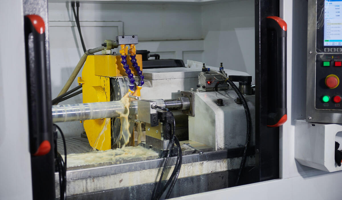
Types of electric motor rotors
At Zhenli Motor, we design and manufacture a wide range of electric motor rotors tailored for various industrial, commercial, and automotive applications. Each type of rotor has a unique structure, working principle, and set of advantages that determine its suitability for specific performance, speed control, and torque requirements.
Squirrel cage rotor
This is the most commonly used rotor type, especially in AC induction motors. It is known for its rugged design, simplicity, and low maintenance requirements. A squirrel cage rotor consists of a laminated steel core with embedded aluminum or copper bars arranged in parallel. These bars are short-circuited by end rings on both sides, forming a closed-loop circuit. When the stator’s rotating magnetic field interacts with the rotor, it induces current in the bars, producing torque and rotation.
Since there are no brushes or external electrical connections, squirrel cage rotors are highly durable and reliable. However, their speed and torque control are limited unless paired with variable frequency drives (VFDs). They are widely used in fans, pumps, blowers, compressors, and standard industrial machines.
Wound rotor
Wound rotors offer greater control and are ideal for heavy-duty applications that require variable speed and high starting torque. In this type, copper windings are placed in slots in the laminated core, and brushes with slip rings connect the windings to external resistors. Adjusting the external resistance allows control over rotor current, torque, and acceleration.
Though more complex and maintenance-intensive than squirrel cage designs, wound rotors are preferred in applications such as cranes, elevators, hoists, and mills, where high load capacity and smooth starting are critical.
Permanent magnet rotor
Permanent magnet rotors are used in modern synchronous and brushless DC motors. They provide high efficiency, precise speed control, and compact design — making them ideal for advanced and space-saving applications. These rotors use powerful magnets, often made of rare-earth materials such as neodymium, mounted either on the surface or inside the rotor core.
The magnetic field from these magnets interacts with the stator’s rotating field to produce synchronous rotation with minimal energy loss. Permanent magnet rotors are widely used in electric vehicles, robotics, HVAC systems, drones, and other devices requiring compact size and high performance. However, they tend to be more expensive and have lower heat resistance than induction types.
Salient pole rotor
Salient-pole rotors are primarily used in low-speed synchronous machines designed for high-torque, constant-speed applications. Their structure features large poles projecting outward from the rotor core, each wrapped with DC-excited field windings. The rotor locks in synchrony with the stator’s magnetic field, ensuring constant rotational speed.
These rotors are efficient at low speeds and are commonly used in hydroelectric power plants, marine motors, and synchronous condensers. Due to their size and construction, they are not suitable for high-speed operation.
Cylindrical rotor
Cylindrical or non-salient pole rotors are designed for high-speed synchronous machines where smooth and stable rotation is required. They feature a sleek, cylindrical form with longitudinal slots for the rotor windings. Unlike salient pole rotors, they do not have protruding poles and are dynamically balanced for high-speed operation, often exceeding 3,000 RPM.
Cylindrical rotors are ideal for turbo-generators in thermal and nuclear power plants, gas turbines, and other high-speed systems that demand precision and reliability. Their streamlined structure minimizes windage losses and ensures long-term mechanical stability.
DC motor rotor (armature)
In DC motors, the rotor — also called the armature — contains windings inserted into slots on a laminated iron core. A commutator on the shaft reverses current flow through the windings, allowing continuous rotation and smooth torque output. This configuration provides excellent speed regulation and strong starting torque, making it suitable for conveyors, rolling mills, and electric traction systems.
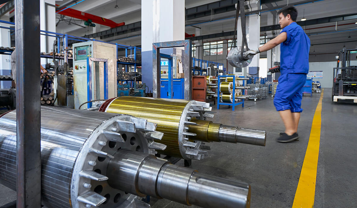
How the rotor works in an electric motor
The rotor plays a central role in converting electrical energy into mechanical motion. Its operation is based on electromagnetic principles — the interaction between magnetic fields and electric currents creates the rotational force (torque) that drives machines and devices.
Magnetic field interaction
The interaction between the rotor and the stator’s rotating magnetic field (RMF) is the core of rotor operation. When electrical power is applied, alternating current flows through the stator windings, creating a rotating magnetic field. This field crosses the air gap between the stator and rotor, constantly changing direction and intensity. As the magnetic field sweeps across the conductive elements of the rotor (bars or windings), it induces a current according to Faraday’s Law of Electromagnetic Induction — a changing magnetic field within a closed circuit generates an electromotive force (EMF).
Induced current and torque generation
The torque that causes the rotor to spin is generated through the interaction of magnetic fields. In induction motors, the rotating magnetic field induces a current in the rotor’s conductive bars or windings. This current generates its own magnetic field, which interacts with the stator field to produce motion. The resulting torque is described by the Lorentz force principle — a current-carrying conductor in a magnetic field experiences a force. The direction of this force (and thus rotation) follows the right-hand rule.
In squirrel-cage rotors, the induced current produces continuous torque, whereas in wound rotors, external resistors connected via slip rings allow more precise control over current, torque, and acceleration.
In synchronous motors (including permanent magnet types), the rotor creates its own magnetic field — either from direct current excitation or permanent magnets. The rotor locks in step with the stator’s magnetic field, rotating at the same speed with zero slip, ensuring precise speed control.
Slip and speed regulation
In induction motors, the rotor never spins exactly as fast as the rotating magnetic field. This speed difference is known as slip and is essential for inducing current and generating torque. Without slip, no relative motion would occur between the magnetic fields, meaning no current or rotation. Slip adjusts automatically with load — when torque demand increases, slip increases slightly to maintain balance between magnetic forces and mechanical load.
Direction of rotation
The rotor’s direction of rotation depends on the phase sequence of the power supplied to the stator. In three-phase motors, reversing any two phases reverses the direction of the rotating magnetic field, causing the rotor to spin in the opposite direction. This makes it simple to change rotation direction in applications such as conveyors, pumps, and elevators.
Startup and acceleration
When the motor is first energized, the rotor is stationary while the stator’s magnetic field is already rotating. This difference in speed induces a strong current in the rotor, creating a large starting torque that initiates motion. As the rotor accelerates, slip decreases, reducing the induced current until a steady operating speed is reached. Some motors incorporate soft starters, capacitors, or external resistors to achieve smoother acceleration and protect against excessive inrush current.
Synchronous operation
In synchronous motors, the rotor operates differently. Instead of relying on induction, it maintains a magnetic field via direct-current excitation or permanent magnets. Once synchronized, the rotor turns at the same speed as the rotating magnetic field — no slip occurs. This type of motor is ideal for applications requiring precise and constant speed, such as CNC machines, robotics, and timing equipment.
Applications of electric motor rotors
Electric motor rotors are utilized in a wide range of applications across various industries, and their design and materials have a direct impact on motor performance, including efficiency, speed, torque, and power density. A well-engineered rotor maximizes electromagnetic interaction, minimizes energy losses, and enhances durability — ensuring optimal performance for its intended use.
Applications of different rotor types
- Squirrel cage rotor: Known for its rugged and maintenance-free design, the squirrel cage rotor is widely used in industrial machinery, pumps, fans, compressors, and HVAC systems. Its simple structure offers high reliability, efficient operation, and cost-effectiveness, making it ideal for continuous-duty applications.
- Wound rotor: Equipped with windings connected through slip rings, the wound rotor provides adjustable speed and high starting torque. It is commonly used in heavy-duty applications such as cranes, hoists, mills, and elevators, where torque control and smooth acceleration are essential.
- Permanent magnet rotor: Designed with embedded or surface-mounted magnets, this type delivers high efficiency, compact size, and low energy losses. It is extensively used in electric vehicles (EVs), robotics, home appliances, and portable equipment due to its superior torque-to-weight ratio and energy-saving capabilities.
- Salient-pole rotor: Featuring large, projecting poles with concentrated windings, the salient-pole rotor is ideal for low-speed, high-torque applications such as hydroelectric generators, wind turbines, and synchronous motors in renewable energy systems. It provides strong field excitation and excellent load control.
- Cylindrical rotor: With a smooth cylindrical surface and distributed windings, this rotor type is designed for high-speed operations and is typically used in turbo-generators, gas turbines, and power plants where stability and efficiency at high rotational speeds are critical.
Broader industrial and commercial use
Electric motor rotors play an essential role across major industries:
- Industrial machinery: Powering conveyor belts, pumps, compressors, and machine tools with consistent torque and durability.
- Transportation: Used in electric vehicles, trains, and elevators that demand high efficiency and torque output.
- Home appliances: Found in fans, washing machines, vacuum cleaners, and refrigerators, offering quiet and efficient operation.
- HVAC systems: Ensuring reliable temperature control and energy efficiency in air conditioners and heaters.
- Robotics and automation: Permanent-magnet rotors enable precise control in robotic arms and automated assembly lines.
- Renewable energy: Advanced rotor designs improve the performance of wind turbines and hydroelectric generators, supporting sustainable energy production.
Conclusion
The rotor is the heart of every electric motor, converting electrical energy into mechanical motion and ensuring reliable performance across countless applications. Its design, materials, and construction quality directly affect the motor’s efficiency, torque, speed, and overall durability. As industries move toward smarter and more sustainable technologies, the rotor’s importance in achieving energy efficiency and long-term reliability continues to grow.
From electric vehicles and renewable energy systems to industrial machinery and home appliances, the evolution of rotor technology shapes the future of modern motion.
As part of a professional electric motor manufacturer in China, Zhenli Motor is dedicated to providing high-quality, precision-engineered rotor solutions that meet the diverse needs of today’s industries. Whether you need a custom rotor design or expert assistance in selecting the right type for your application, our team is ready to help. Contact Zhenli today to discover how our advanced manufacturing capabilities can help you build motors that perform efficiently, reliably, and sustainably.