
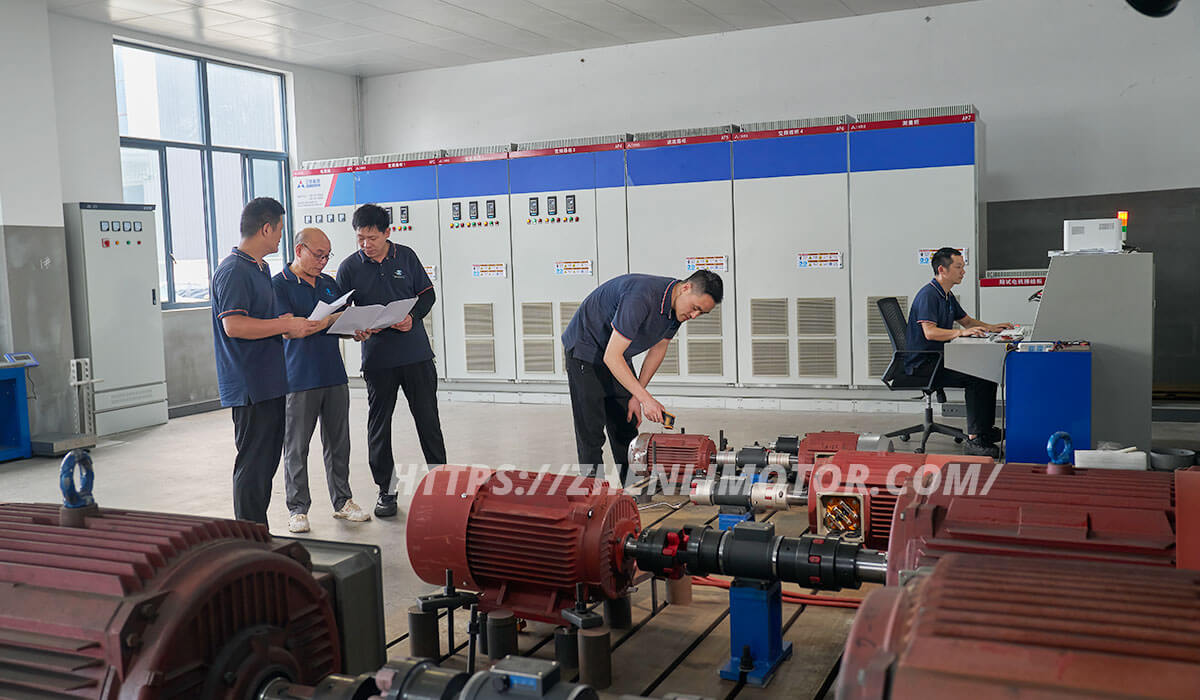
Electric motors are everywhere — powering everything from home appliances and office equipment to electric vehicles and heavy industrial machinery. Behind their smooth and efficient operation lies a key factor: speed control. Electric motor speed control plays a critical role in ensuring efficient, reliable, and accurate motor operation. It refers to the intentional regulation of a motor’s rotational speed to match specific operational requirements. From industrial machines to home appliances, adjusting motor speed improves efficiency, reduces energy consumption, and extends equipment life. This control is essential for achieving energy efficiency, precision, safety, and longer equipment lifespan, ensuring that machines perform optimally in any application. Over time, various methods and technologies have been developed to manage motor speed, including mechanical, electrical, and electronic control techniques—each offering different levels of accuracy and flexibility.
With years of expertise in motor technology, Zhenli Motor, a leading electric motor manufacturer in China, continuously develops innovative solutions that enhance performance and reliability across industries. This article explores the fundamental principles, control methods, and modern technologies behind electric motor speed control and how they contribute to greater efficiency and sustainability in today’s motor-driven applications.
Fundamentals of motor speed and torque
To understand how electric motor speed control works, it’s important to first grasp the fundamental relationship between speed, torque, voltage, and current. Every electric motor operates based on the interaction of electrical energy and magnetic fields, which together produce mechanical motion.
In DC motors, the speed of rotation (N) is primarily determined by the applied voltage (V) and the magnetic flux (Φ). The relationship can be expressed as: N ∝ V / Φ
This means that increasing the voltage will raise the motor speed, while increasing the magnetic flux (by strengthening the field) will reduce it. Torque (τ), on the other hand, depends directly on the armature current (Ia) and the magnetic flux, given by: τ ∝ Φ × Ia
In AC motors, the speed is linked to the supply frequency (f) and the number of poles (P) in the stator. The synchronous speed (Ns) is expressed by the equation: Ns = 120 × f / P
This formula shows that increasing the frequency results in higher motor speed, while increasing the number of poles lowers it. In real-world applications, induction motors operate slightly below their synchronous speed due to slip, which allows torque production.
Understanding these relationships provides the foundation for effective motor speed control. Electric motors can generally be categorized into three main types:
- DC motors, which include brushed and brushless designs known for their precise speed regulation.
- AC induction motors, widely used for their durability and cost-efficiency.
- Permanent Magnet Synchronous Motors (PMSM), which combine high efficiency with excellent performance in variable-speed applications.
Each motor type responds differently to control methods, making it essential to match the right motor and control system to the intended application.
Speed control methods for DC motors
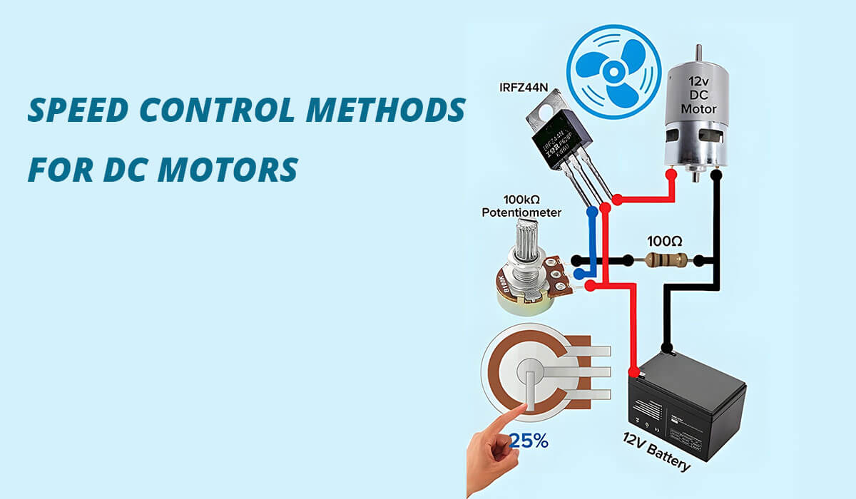
DC motors are widely used in applications requiring precise and flexible speed control. Their ability to adjust speed smoothly and maintain strong torque performance makes them ideal for machinery, vehicles, and automation systems. Depending on the motor type, load factors, and intended performance, several methods can be used to control an electric motor’s speed by varying the electrical input to achieve the desired speed and torque levels. The most common speed control methods for DC motors include (1) armature voltage control, (2) field flux control, (3) armature resistance control, and (4) pulse width modulation (PWM) and electronic commutation.
Armature voltage control (below base speed)
This method regulates motor speed by adjusting the voltage applied to the armature while keeping the field flux constant. Since speed is proportional to the armature voltage (N ∝ V/Φ), increasing voltage increases speed up to the motor’s rated or base speed. This allows smooth variations, especially at low speeds. It is often achieved using DC-DC converters or thyristor-based drives.
Advantages:
- High efficiency, excellent speed regulation, and full torque at low speeds.
Disadvantages:
- Limited to operation below base speed and requires complex electronic circuitry.
Field flux control (above base speed)
Also known as field weakening, this method modifies the magnetic field’s strength by varying the current in the field winding. Reducing field current weakens the magnetic flux (Φ), which increases speed beyond the rated level but reduces torque. This technique is common in electric vehicles and traction systems that require higher speeds intermittently.
Advantages:
- Enables operation above base speed without increasing voltage.
Disadvantages:
- Reduced torque and efficiency at higher speeds.
Armature resistance control
In this method, a variable resistor is connected in series with the armature circuit. Increasing resistance decreases the voltage across the armature, lowering speed. Although simple and inexpensive, this method wastes energy as heat, resulting in poor efficiency. It is used in low-power or temporary applications where fine control is unnecessary.
Advantages:
- Simple and low-cost setup.
Disadvantages:
- Inefficient due to power loss, poor speed regulation, and reduced torque.
Pulse width modulation (PWM) and electronic commutation
Pulse Width Modulation (PWM) is widely used in modern DC and brushless DC (BLDC) motors. It works by rapidly switching power on and off while controlling the average voltage delivered to the motor, providing precise speed control, high efficiency, and low heat generation. BLDC and Permanent Magnet Synchronous Motors (PMSM) use electronic commutation instead of mechanical brushes, switching current electronically in synchronization with rotor position.
Advantages:
- Precise speed and torque control, high efficiency, long lifespan, and low maintenance.
Disadvantages:
- Higher initial cost and complex control electronics.
Speed control methods for AC motors
AC motors are the backbone of modern industry due to their durability, simplicity, and efficiency. However, controlling their speed can be more complex than in DC motors because their speed depends on both the supply frequency and the number of poles. Over the years, several techniques have been developed to achieve reliable and efficient AC motor speed control, ranging from traditional mechanical methods to advanced electronic systems. For AC motors, particularly induction types, these methods vary depending on the application, load conditions, and performance requirements.
Variable voltage, variable frequency (V/f) control
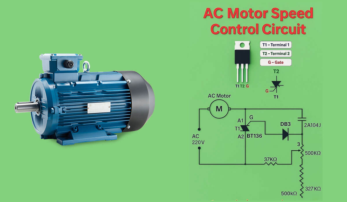
The most effective and commonly used method for AC motor speed control is the Variable Frequency Drive (VFD). Since motor speed is directly proportional to the supply frequency, VFDs can offer broad and seamless control. The V/f control method maintains a constant ratio between supply voltage (V) and frequency (f), ensuring that the magnetic flux remains stable. When frequency increases, voltage increases proportionally, allowing speed adjustment without overmagnetizing or underpowering the motor.
- Applications: Pumps, fans, conveyors, manufacturing, water treatment, and HVAC systems.
- Advantages: Smooth speed variation, energy efficiency, and good torque control.
- Limitations: Moderate dynamic performance and less precise torque control compared to vector control.
Vector control (field-oriented control)
Vector Control, also known as Field-Oriented Control (FOC), is an advanced method designed to achieve DC motor-like performance in AC motors. It decouples the torque and magnetic flux components, allowing independent control through real-time feedback and mathematical transformations. This ensures precise control over torque and speed even during rapid load or speed changes.
- Applications: Robotics, CNC machines, electric vehicles, and high-performance industrial drives.
- Advantages: High torque accuracy, fast response, and excellent low-speed performance.
- Disadvantages: Complex control algorithms and higher cost.
Direct torque control (DTC)
Direct Torque Control (DTC) is another advanced technique that directly regulates the motor’s torque and flux without using modulation or transformations. It continuously monitors motor parameters and instantly switches inverter states to achieve desired torque and flux.
- Applications: High-performance drives, traction systems, and automation systems requiring quick response.
- Advantages: Rapid torque control, high efficiency, and reduced system complexity.
- Disadvantages: Torque ripple and noise at low speeds.
Rotor resistance control (for slip-ring motors)
In wound-rotor or slip-ring induction motors, speed can be adjusted by adding external resistance to the rotor circuit. Increasing resistance increases slip, reducing motor speed while improving torque at lower speeds. Although effective for specific applications, this method is inefficient because much of the energy is lost as heat in the resistors.
- Applications: Cranes, hoists, and elevators requiring high starting torque.
- Advantages: Simple and reliable for heavy-load starting.
- Disadvantages: Inefficient due to energy loss, mechanical wear, and limited precision.
Voltage control (for single-phase motors)
Voltage control is primarily used for single-phase AC motors under light loads. By reducing supply voltage, both torque and speed are decreased. However, excessive voltage reduction can affect motor stability and efficiency.
- Applications: Fans, blowers, and small appliances.
- Advantages: Simple and low-cost method.
- Disadvantages: Reduced torque and unstable operation at low voltages.
Pole changing method
The pole-changing method provides discrete (stepwise) speed control by altering the number of magnetic poles in the stator winding. Changing the pole count changes the synchronous speed (Ns = 120f/P). This is done through special switchgear or a Dahlander connection.
- Applications: Multi-speed fans, pumps, and machine tools that require two or more fixed speeds.
- Advantages: Simple design and reliable operation.
- Disadvantages: Limited flexibility — allows only fixed speed levels, not continuous variation.
Open-loop and closed-loop control systems
Modern electronic speed control systems have transformed how electric motors operate, offering precise, efficient, and flexible performance across various applications. Unlike traditional mechanical or manual methods, today’s systems rely on electronic hardware and digital algorithms to regulate voltage, frequency, and current with high accuracy. These systems operate mainly in two configurations: open-loop and closed-loop, depending on whether they monitor the motor’s output and adjust automatically.
Open-loop control
In an open-loop system, the controller sends a fixed command to the motor without receiving feedback. The motor runs at a speed determined by the input signal, but there is no correction mechanism if load conditions or external factors change. This setup is simple, low-cost, and effective where precision isn’t critical.
- Examples: Basic fans, pumps, and simple conveyor systems.
- Advantages: Low cost, simple setup, and fewer components.
- Disadvantages: No automatic correction, limited accuracy, and performance affected by load variations.
Closed-loop control
Closed-loop systems continuously monitor motor parameters such as speed, torque, or position using sensors. Feedback is sent to the controller, which compares the actual output with the desired setpoint and adjusts input signals to maintain consistent performance. If the load changes, the system compensates automatically to sustain the target speed or torque.
- Examples: Robotics, CNC machines, and advanced manufacturing systems.
- Advantages: High accuracy, consistent performance, and energy efficiency.
- Disadvantages: Higher cost and more complex electronics.
Key hardware components
Modern control systems use advanced hardware like Variable Frequency Drives (VFDs), inverters, and DC drives to regulate motor performance.
- VFDs convert fixed-frequency AC input into variable-frequency output, allowing smooth speed variation and torque stability.
- Inverters convert DC to AC with adjustable frequency and voltage for both AC and DC motor control.
- DC drives electronically control armature voltage and field current for precise DC motor speed control.
Pulse width modulation (PWM) technique
At the core of modern electronic control is Pulse Width Modulation (PWM), a technique that finely regulates voltage and current delivered to the motor. PWM rapidly switches power devices on and off, varying the pulse width to control the average voltage. This enables smooth operation, minimal heat generation, and longer motor lifespan.
Integration with modern technologies
Contemporary control systems integrate microcontrollers, sensors, and IoT technologies to enable smarter, more adaptive operation. Microcontrollers run algorithms that optimize torque, speed, and energy efficiency in real time. Sensors track parameters like temperature, vibration, and load. With IoT connectivity, systems enable remote monitoring, predictive maintenance, and fault detection — ensuring reliability and reduced downtime.
Factors Affecting Motor Speed
The speed of an electric motor is influenced by several interacting factors, including voltage, current, magnetic flux, motor type, load, and control system design. Understanding how each of these elements affects motor performance is essential for maintaining efficiency, precision, and reliability in any application.
1. Voltage, current, and magnetic flux
For most electric motors, speed is directly related to voltage and inversely related to magnetic flux. In a DC motor, increasing the supply voltage raises the speed because the armature receives more electrical energy. Conversely, increasing the magnetic flux (by strengthening the field) reduces speed since a stronger magnetic field produces greater opposition to armature rotation. In AC motors, speed depends on the frequency of the input power, as expressed in the equation Ns = 120 × f / P. Adjusting the supply frequency, therefore, directly changes the motor’s rotational speed.
2. Motor type
Different types of motors respond uniquely to control inputs. DC motors offer fine speed regulation by adjusting voltage or field current, making them ideal for applications that require variable speed and high precision. AC induction motors, on the other hand, typically operate at a nearly constant speed determined by the supply frequency and the number of poles. However, with the use of variable frequency drives (VFDs), AC motors can now achieve flexible and efficient speed control. Permanent Magnet Synchronous Motors (PMSM) combine the benefits of both types, offering high torque density and excellent speed stability under electronic control.
3. Load variations
Motor speed naturally varies with the load applied to the shaft. When the load increases, the motor must draw more current to maintain torque, which may cause a slight reduction in speed. In DC motors, excessive load can cause a significant drop in speed, while AC induction motors experience an increase in slip. Maintaining a proper match between motor capacity and load demand is key to stable operation and energy efficiency.
4. Environmental conditions
External factors such as temperature, humidity, and air quality can also impact motor speed and performance. High temperatures can affect winding resistance, while dust or moisture may interfere with cooling or mechanical movement, leading to reduced efficiency and unstable speed. Ensuring adequate ventilation and protection in harsh environments helps maintain consistent operation.
5. Control system and feedback mechanisms
Modern motor systems often include feedback mechanisms such as encoders, tachometers, or sensors that monitor speed and adjust input signals automatically. These closed-loop control systems improve accuracy and responsiveness by continuously comparing actual speed with the desired value. In contrast, open-loop systems operate without feedback, making them simpler but less precise.
Conclusion
Electric motor speed control plays a crucial role in ensuring efficiency, precision, and high performance across various applications. In any system involving motors, controlling speed is essential for achieving accuracy, longevity, and energy savings. From industrial machinery to home appliances, understanding how to manage motor speed enables better performance and reduced power consumption.
As industries move toward smarter technologies, advancements such as IoT integration, AI-based optimization, and wide-bandgap power electronics (SiC and GaN) are making speed control systems more intelligent, sustainable, and adaptable to evolving demands.
As part of a professional electric motor manufacturer in China, Zhenli Motor is dedicated to providing innovative and reliable control solutions that meet global standards. We combine advanced technology, manufacturing expertise, and industry experience to help our clients achieve optimal motor performance in every application.
Partner with Zhenli Motor today — your trusted expert in electric motors.